

Japan Activity Report PDF
The total amount of construction investment of tunnels and underground spaces was about 17.5 billion USD. Some 62% are for roads, 16% for waterways, 12% for railways and others.
The followings are some instances of new tunnel construction methods developed in Japan.
(1) Rapid Excavation by SENS in Unconsolidated Water-bearing Ground *
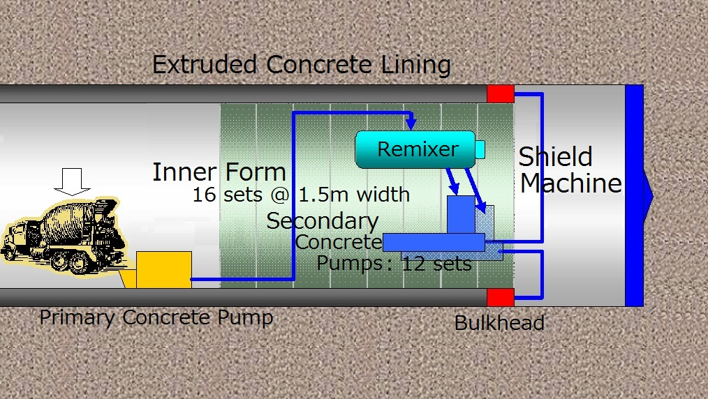
SENS is the extruded concrete lining system with shield.
The Tsugaru Yomogita Tunnel is constructed on the Hokkaido Shinkansen line. It is 6,190 m long with a double-track.
The geology is mainly composed of unconsolidated water-bearing sand. Frequent soil collapses and quicksand were reported in previous tunnelling in this area. The major issues of this tunnel were how to maintain stability of the face and to shorten the construction period. As for these requirements, SENS, a mechanized tunnelling method, was developed and improved instead of conventional tunnelling method.
The primary lining concrete used in the SENS is pumped and filled into a narrow space simultaneously with advance of the shield machine, imposing following requirements: high fluidity, low viscosity, strength at an early stage and freshness for a long time. The performances of concrete and also mechanical equipments were improved.
As a result, construction cost was almost the same as that of conventional tunnelling method. A monthly average advance was 190 m and the maximum monthly advance was 367.5 m.
Fig. 1: Concept of SENS
(2) Enlargement of Shield Tunnels *)
Most of the Yokohama Circular Northern Expressway is underground, including twin tubes of 5.5 km shield tunnels with outer diameter of 12.3 m.
In the middle of the tunnels, there are four ramps for entrance and exit. The main shield tunnels have to be enlarged to connect with the ramp shield tunnels. However, cut and cover method is not available for the enlargement, because of the deep overburden of tunnels and the highly developed residential area above the ramps.
The geology in the enlargement area is mainly composed of hard mudstone and sandy mudstone with uniaxial compressive strength 1MPa or more. They contain sand and sandstone layers with N value 50 or more. The maximum water pressure of the sand layer is 0.5 MPa and the coefficient of uniformity is relatively low (around 6), so quicksand could occur if groundwater is discharged through the layer.
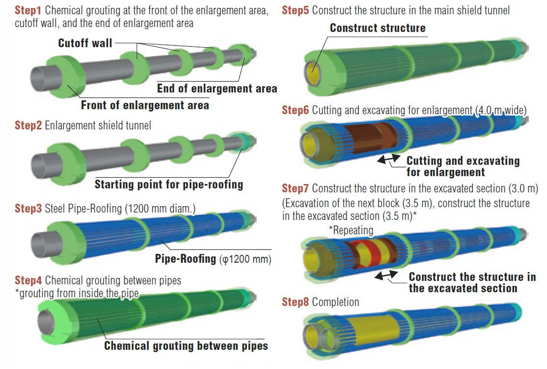
The new technique has developed and was applied to enlarge shield tunnels. The concept of work sequence is shown in Fig.2. At first, chemical grout is carried out at the front, the end and several sections in the enlargement area from the main shield tunnel (Step-1). At the front section, the station for the pipe-roofing is constructed (Step-2). Steel pipe-roofing is placed in the longitudinal direction and covers the enlargement area (Step-3).
Then the chemical grout is injected between the pipes (Step-4). Thus the enlargement area is enclosed by pipe-roofing and chemical grouted zones to ensure water tightness. Partial segment rings of the main shield tunnel is removed and the ground within the pipe-roofed zone is excavated (Step-6). After the permanent lining concrete is placed, the next adjacent block is constructed repeatedly (Step-7).
Fig. 2 Work Sequence
[Reference] *): “Tunnelling Activities in Japan 2014”, JTA